
After creating a custom module prototype for my TI-92 calculator, I felt it still needed some work. Indeed my contraption did work. But it was so clunky I could not close the calculator anymore, not to mention the pain it was to change the ROM inside it 
So my next goal was set, create a small enough module, so it could fit in the calc when closed. Moreover it would have to be easy to reflash and cheap to build for anyone !
I’m pretty happy with what I came up with, and I’ll walk you through my journey creating it 
Everything that I talk about here is opensource and can be downloaded from my Git instance or Github.
Design decisions
My first idea was to have an all in one module: It would have been the size of a regular module and could have been reflashed with a USB port on it, through an on-chip MCU, that would have made the bridge between the PC and the EEPROM memory.
Even though it seemed like the perfect solution, it would have been a little bit too complex for my current embedded skills  It would have required to design the whole circuit around the MCU such as the power management unit, clocks, and even USB communication. That’s something I look towards learning, but not yet for this project.
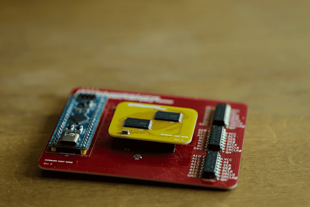
So the design I went with, is a two boards design. The first board is the actual module that goes into the calc, it has the same size as a usual Texas Instrument module and only contains the two EEPROM chips. And the second board is the flasher/programmer which you plug the module onto so it can be rewritten. This allows me to have a bigger PCB for the flasher on which I can fit a whole MCU devkit which already has power management unit, clocks, etc.
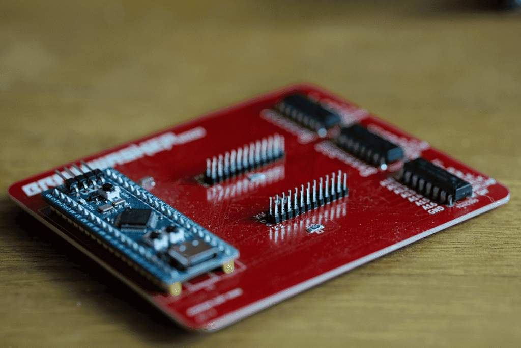
Now before building anything I had to choose the parts I would use for this project. For the EEPROM I stayed with the SST39SF040, just in a smaller form factor. For the devkit I had to have 19 address pins, 2x 8 data pins, and 3 control pins. 38 GPIO is A LOT of pins, but come on, there might be some decent devkit option out there… Well, There is, but you better not look at the price  So instead I went with shift registers, these are lil chips that you can chain together to gain more output pins, for example for the address pins. With that I could take a smaller devkit, and I chose the STM32 Bluepill which is a really common unofficial devkit. I found mine for 2-3€ on AliExpress, which is like crazy cheap !
Designing the PCB + My take on LLM
Once again I designed my PCB with KiCAD, which is a really great open source software. This time I tried to create a better quality PCB by creating ground planes which help reduce electrical noise and it’s generally a good practice in PCB design. I also placed some capacitor to help filter out the current noise 
I also discovered you could just drop the project files into Claude for checking, and it worked really well. It’s able to detect the nets and find if there is any odd stuff that you misplaced. I know LLMs are a polarizing topic in the maker world, but I think we really need to embrace them as tools to help us create stuff. Of course making everything with AI destroys the fun that comes from building cool shit. But at the same time I’m convinced that if it can help you save money (for example PCB checking) or save time on task you don’t enjoy, you should use it 
Furthermore I think it’s a great tool when it comes to self learning. I personally use it all the time at school when I need to revise for my exam. If prompted correctly it can become a great tutor and help you understand almost anything. This is for me the best part about this new tech, it helps spreading knowledge to the ones who seeks it  , and all of that for free (at least for now).
For this project I mainly used it as a pal I could seek advice from, when it comes to electronics. All of this is really new to me so it helped me a ton. I personally enjoy programming, and I even consider it as a form of art, therefore all the code is by me. I like the code how I write it, so no LLM will touch mine. It’s the same for the artistic side (we’ll get to this in a bit), it’s mine, and no AI will ever be able to replace human artists.
Getting my PCB manufactured
Now that my PCB design is done it’s time to get it manufactured !
This project was made possible by PCBWay who were kind enough to send me free PCB prototypes. The process of getting them manufactured is extremely smooth and straight forward thanks to their intuitive website !
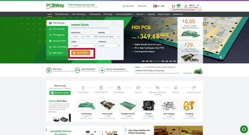
You first go to their website : https://www.pcbway.com/, and then click the Quote Now button, and then the Quick Order one
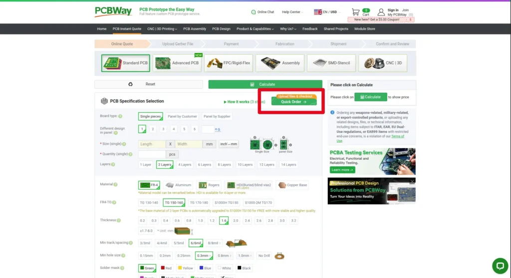
You can then upload the gerber files you generated with your favorite software, and see the PCB preview with a bunch of options. Most of them are great with the default value, and you can choose a custom color if you wish.
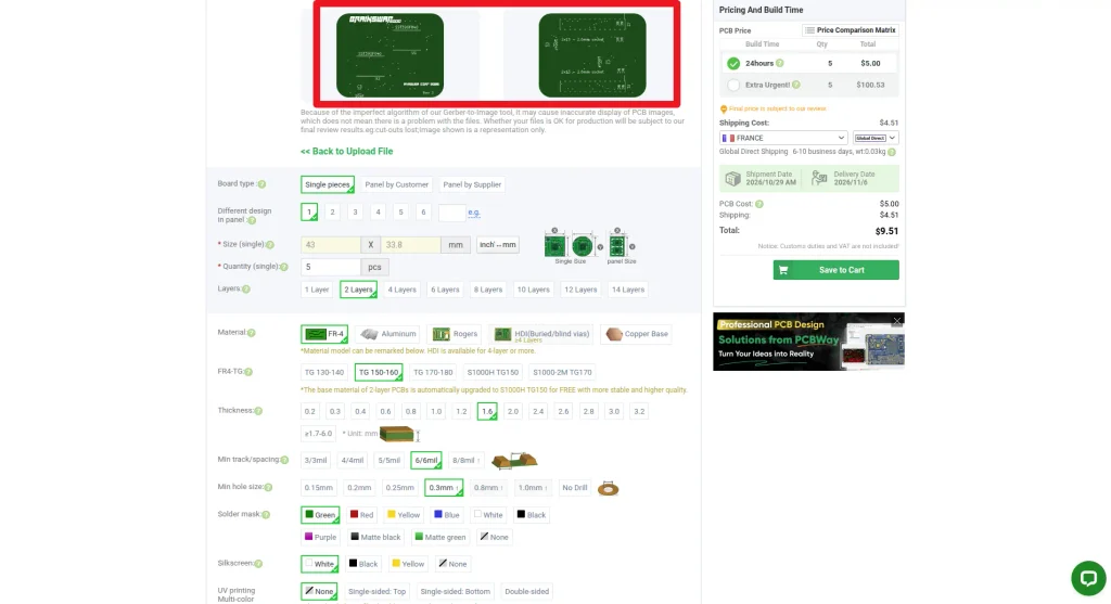
It’s always fascinating to me how cheap it can be to have a professionally made PCB with such an easy process. I got the PCB delivredred to my door fairly quickly, and the quality of it is perfect. None of the track were cut and it was perfectly functional.
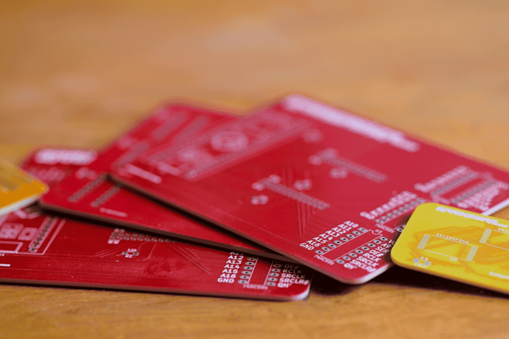
If you want to directly order them I created two PCBWay projects you can order from :
The Brainswap module

The Brainwasher board
So thank you to PCBWay for helping me with this project, and don’t hesitate to check their service if you need any PCB made 
Coding some stuff
Now that I have everything ready the next step is to develop the software and firmware that will bring life to our lil module !
For the firmware I dug up my old code I made for my Nucleo and tweaked it a bunch to make it work on the new hardware. One of the biggest change I made was the address pin write. Thankfully these shift registers are meant to work with SPI and the STM32 HAL provides some helpful function to make it work.
The other more complicated things to tackle were the USB communication. On the bluepill I could not use the USB UART interface anymore and that was a real pain to solve Instead I had to use USB CDC which simulates a COM port on the host PC. Thankfully ST has a driver for it, however I had some issues with their weird implementation, so I had to tweak a few things. But with a bit of struggle I managed to get it working.
The only part now left was to create the PC app that would communicate with it. In my previous project I used minicom which worked decently for a prototype but was clearly not good enough for a final product. So to the drawing board I went and I designed a protocol that would enable the software to do all sort of things, and more importantly verify its data integrity. Here is a schematic I made that illustrates it quite well.
|============Header===========|===packet===|=Footer==|
+---------+---------+---------+------------+---------+
| MagicNB | Type    | ID      | Extra data | CRC32   |
| 4 bytes | 2 byte  | 2 byte  | ?? bytes   | 4 bytes |
+---------+---------+---------+------------+---------+
MagicNB = 1337_4267h, this is to say that the packet starts
Type = This says what the packet will do:
    - 0 : Acknowledge the packet with ID
    - 1 : Erase chip
    - 2 : Send file to ROM
    - 3 : Receive file from ROM
    - A : Data packet (This can come from the PC or the ROM)
ID = Unique packet ID, it can be used to acknowledge another packet
Extra data = This is the core data such as binary data for example
CRC32 = Checksum that verify the packet integrity

Extra data:
    Acknowledge packet:
    +---------+---------+---------+
    | Header  | Status  | Footer  |
    | 8 bytes | 2 bytes | 4 bytes |
    +---------+---------+---------+
    Status :
         - 0 : All good buddy
         - 1 : Invalid checksum please resend
    Data packet:
    +---------+---------+-----------+---------+
    | Header  | Address | Data      | Footer  |
    | 8 bytes | 4 bytes | 128 bytes | 4 bytes |
    +---------+---------+-----------+---------+
The packets don’t have a fixed length, it depends on the packet type. For example an order packet, like erase chip contains no external data whereas a data packet contains an address and a data field.
Every packet has a CRC32 checksum to ensure the data integrity.
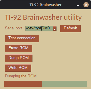
After all of this was laid out, I created an app around it to make it easier for anyone to use. I decided to use Python as it’s cross platform and has an easy to use serial lib. For the GUI I searched a bit at what was possible, and came across PySimpleGUI. I didn’t want to waste time on UI and this lib did the job perfectly. Here is the result
Finishing touch
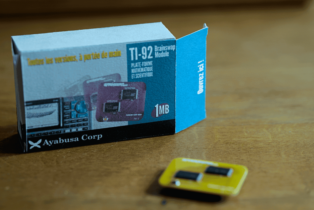
After some testing and debugging I managed to get everything working. But before releasing everything to y’all I decided to create a little packaging for my module, because why not !
I took my inspiration from the original TI-92 box to create mine with a retro look. And after some work in Inkscape, here is the result ! I’m pretty happy about how it turned out
Conclusion
With the PCB, firmware, software and even box being done, I consider I have accomplished my job and finished this project ! During this project that spanned over almost a year I learned a ton about embedded stuff, and it reinforced my will to work in this field. I’ve got a lot left to learn, and I’m eager to increase my knowledge on the topic
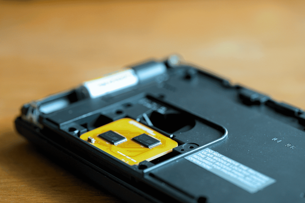
There is of course still room for improvement, at this stage the module can fit inside the calc, and can be reflashed/dumped quite easily with the programmer. However it only supports OS that fit inside regular modules, with the most up to date version being the 1.12. So it does not support the TI-92 II module nor the TI-92 Plus one.
I did a bit of reversing on the TI-92 Plus module and I think it’s definitely possible to do, however it would still require a bunch of work. You would need to find recent replacement for the RAM and ROM chips. The hardest part being the ORBIT chip which is a custom made ASIC for this module . From what I understood while probing it’s responsible for choosing which chip (RAM or ROM) is activated and can talk to the calc.
However even if this seems like a cool project I need to take a break with the TI-92. So feel free to borrow what I learned in these article / source code and make yours ! As I said at begining you can grab everything from my Git instance or Github.
Thanks again to PCBWay for sending me their PCBs, and don’t hesitate to check out their services !
Thanks to TI-Planet for their help when I broke my TI-92 Plus module, and shoutout to Critor, who I met at the 2026 APMEP’s JN and who is running this great forum.
And as always thank you for taking the time to read this blog, it means a lot
– Ayabusa