
Note – educational only.
I’m sharing this write-up to show what I learned while experimenting with my Numworks n0120. I won’t publish or redistribute any Numworks binaries or proprietary code, and nothing here is meant to help bypass security or violate the device’s license. This is personal research, do it at your own risk. I have no affiliation with NumWorks and this post isn’t endorsed by them.
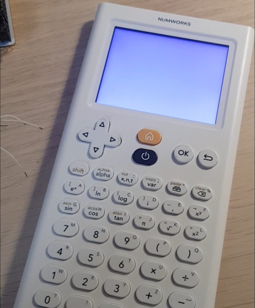
Hi guys! It’s been a while since I posted on this blog, but I’m back! So last time I wrote an article on my attempt to create an OS for the Numworks from scratch, go check it out if you missed it! Long story short I created a CFW (Custom firmware) that could turn on the LED and get keyboard inputs. I called it Zeta OS. But sadly I was not able to create the drivers for the screen as it’s a quite complicated task and I was just starting in embedded systems. After a few weeks I dropped this project and went back to other stuff… Until now, I recently won a game jam focused on calculator on the french forum Ti-Planet with my game A la carte. And they kindly awarded me with a Numworks n0120, the latest and most powerful model !!!
What’ new on this model?!
So what’s new with this new n0120 model? Well, the first thing is that there aren’t any CFW, unlike the n0110 where there is a wide ecosystem of bootloaders, OS, and even a jailbreak. And all of that is because Numworks stopped being fully open source, so no driver, no schematics, we’ll have to do everything ourselves! First thing first, before any hacking let’s open the beast and see what’s inside:
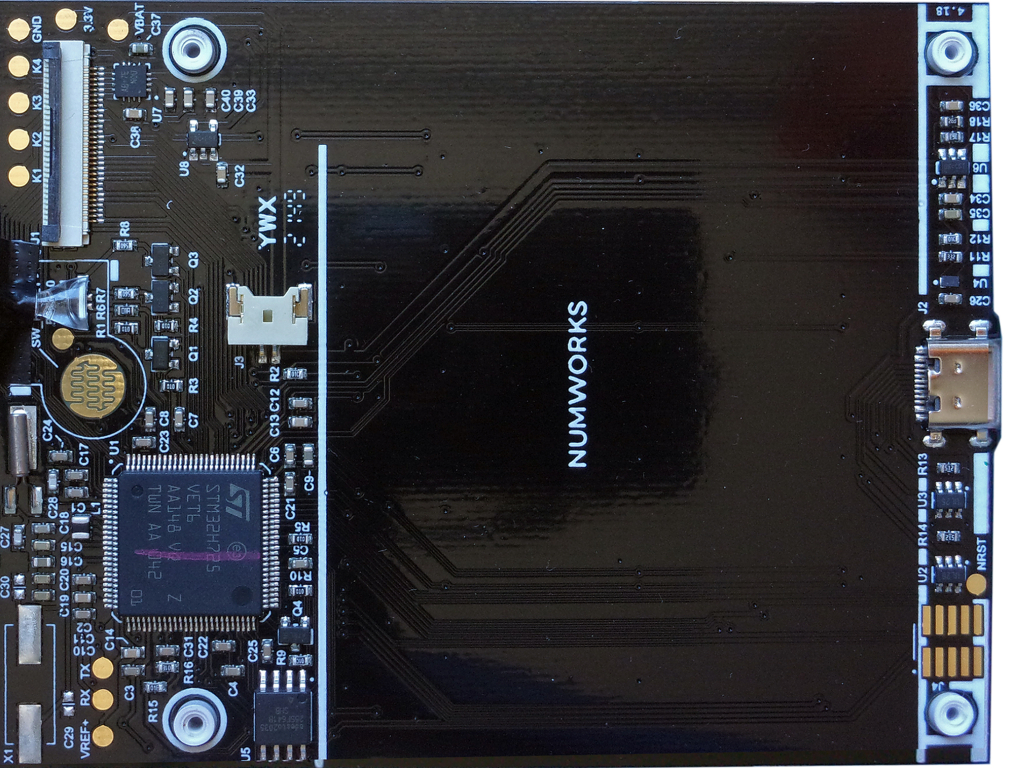
The PCB is very similar to the n0110, here is what we can see:
- The new MCU “STM32H725”, which is a much more powerfull than the old one, and still holds the bootloader
- The new USB-C plug, it’s nice to finally have one
- The usual ROM chip which holds our two OS slots
- And finally the debug pins on the bottom right which will be really important later on
Quick recap on Numworks architecture
If you didn’t read my last post here is a quick recap:
The Numworks calculator has 4 main models, the n0100, n0110, n0115, and n0120 (mine). The first two were developed by Numworks when they were still open source, so there is a large variety of CFW and tools for them. But for the 2 last models, the company did not share their drivers nor schematics. And so there are few resources available for them.
On the software side, for the n0110-n0120, there are 2 types of memory:
- The internal memory stored on the STM32 chip, which holds only the bootloader. It’s a small piece of code responsible of verifying and booting in the OS
- And the external memory, stored in a flash chip, which holds two OS slots: slot A and slot B, this enables the calculator to have modded userland and still have a copy of the original OS.
If you are interested you can learn more on this wiki.
Reprogramming the chip
To start doing some fun stuff we first need to get a hand into the MCU. To achieve that I soldered a little adapter that I got from AliExpress to the debug pins which I connected to the ST-Link of my Nucleo F401-RE. Here is the pinout of the debug pins that I determined
+-----+-----+
| 3.3V| JIO |
|     |     |
+-----+-----+
| GND | JTCK|
|     |     |
+-----+-----+
| GND | JTDO|
|     |     |
+-----+-----+
| NC  | NC  |
|     |     |
+-----+-----+
| NC  | NRST|
|     |     |
+-----+-----+
And here is my setup to debug the ST chip
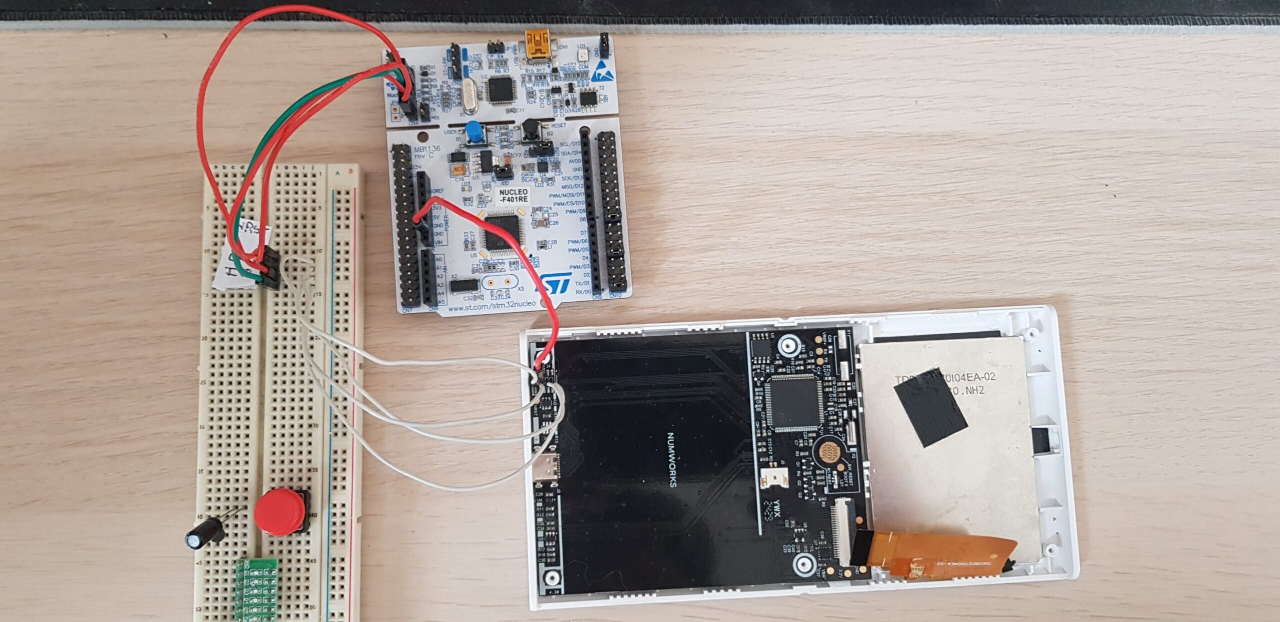
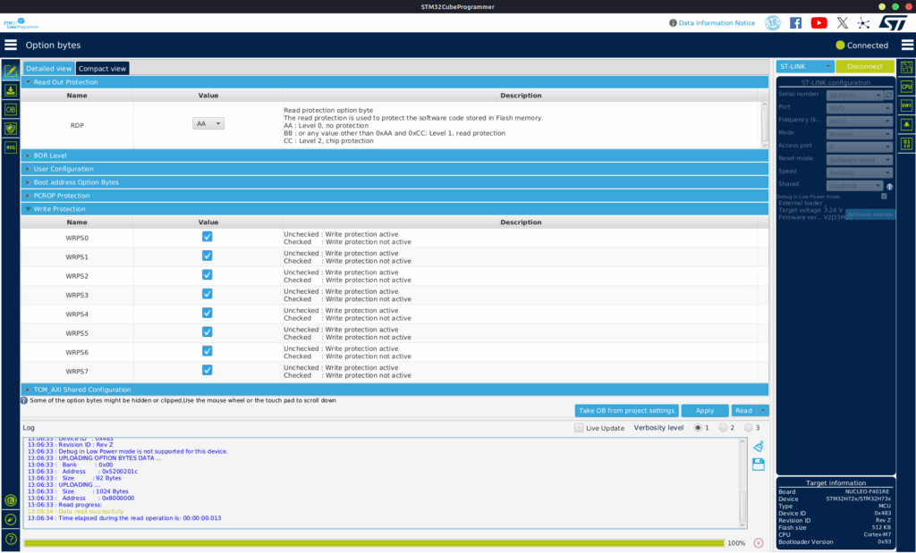
From there we can connect our ST-link (or similar) to our computer and use some software to reprogram our chip. On a locked n0110 you would usually use openOCD, but it’s not the most intuitive tool so I will use STM32CubeProgrammer this time which is really handy and simple to use. Once connected I noticed that I could neither read nor write to the MCU memory after a bit of digging I discovered that this was due to the Read Out and Write Protection settings in the option bytes. So I changed them and bingo it worked, well kind of…
I could read and write to the memory, but everything had been wiped out. And I guess it’s a normal behaviour to avoid people from dumping the firmware. So did I just brick my Numworks 😅, well, luckely no – because NumWorks provides all the necessary binary files on their website using these links
This is the url syntax:
https://my.numworks.com/firmwares/{n0100 | n0110 | n0120}/{stable | beta}.{json | dfu}

So for me it was:
https://my.numworks.com/firmwares/n0120/stable.dfu
Now that we have our DFU (Device Firmware Update) file we need to extract the bin file corresponding to the bootloader. To do this I used this script and extracted the bootloader which is at the address 0x8000000. From there we can open this file using any popular disassembler like IDA, Ghidra, or Binja, as an Arm little endian binary and we should be good to go to reverse some stuff. Something that I observed is that when flashing the stock bootloader, the Numworks would relock itself by reprogramming the write/read protection. To counter that I just NOPed the instruction that would access the Flash_OPTSR_PRG and the Flash_WPSN_PRG1R in both the bootloader and the two slots and it worked. 🎉 I could now flash the bootloader and it would not lock itself so I can now experiment more freely.
Now the reversing
Now that everything is ready I started to do some proper reverse engineering on this bootloader, by labeling functions commenting stuff and reconstructing what this bootloader does. The most critical is the boot process or it would not be called the bootloader. Here is what I determined it does, I won’t go in-depth in the signature checking, as it’s not relevant for our purposes since we already have access to the bootloader
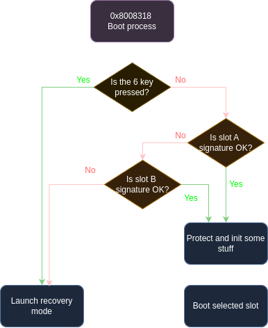
Now the idea is to find a spot where we will stop the program flow and redirect to our code, we could do it at the root of the procedure to be sure to boot in our code, but we would lose the possiblity of going in recovery mode by pressing 6+Reset, and I don’t want to bother recoding this part so instead let’s insert our jump (called a branch in ARM assembly) between the 6 key check and the Slot A verification (when 6 is not pressed). Ok now we know where to place our jump, but where are we going to jump??? In a PC executable it’s always a pain to find a good spot where we will not replace any existing code, it’s usually a region filled with 0s or 0xFFs, which call a code cave. But here it’s quite easy we can just append our code to the end of the data taken by the bootloader, in my case 0x80BC00. So I wrote a little loop program in Thumb2 assembly (some weird ARM stuff) that would just freeze the bootloader when it jumped to it
.syntax unified
    .thumb
    .section .text
    .global routine_start

main:
  NOP
  B   main
Now we just need to compile it to a binary file using the arm-none-eabi toolchain and then copy the generated bytes to the bootloader address 0x80BC00.
arm-none-eabi-as -mthumb payload.s -o payload.o
arm-none-eabi-objcopy -O binary --only-section=.text payload.o payload.bin
So let’s recapitulate what we’ve done so far:
- We NOPed the code that would relock the memory
- We hijacked the code flow of the boot process to jump to 0x80BC00
- And we put our code in 0x80BC00
Now the bootloader freezes but let’s debug our chip to see if everything works as intended. To do so I used openOCD to create a GDB server and then connected to it using gdb-multiarch
$ openocd -f interface/stlink-v2.cfg -f target/stm32h7x.cfg
"======= In another therminal ======="
$ gdb-multiarch
>target remote :3333                  // Connect to the server
>b *0x800bc00                         // Put a Breakpoint at the start of our program
>disassemble /r 0x800bc00, 0x800bc30  // Show the disassembly of our program
And it works!!! Our loop just continue to run indefinitly!
Getting to the fun stuff
A bootloader that just loops is boring and I’m not sure we can call it a bootloader anymore. What I wanted to do is to be able to put some stuff on the screen, get keyboards input, and be able to jump to the slot to still be able to use my calculator.
Hacking the screen driver
As I said at the start of this post, I was discouraged from finishing my OS last time because of the screen which is a really complex part. But this time it’s not gonna defeat me 😋. I adopted a new approach, instead of recreating everything from scratch let’s reuse functions from the existing proprietary bootloader to create our own! The first thing I did was to find the relevant function for my need and the first I found was, f_fill_screen_uniform(color) at 0x8000390 (I came up with the name, there is obviously no names in a disassembly).
So let’s modify our code to call this function
main:
  ldr R4, =0x8005ACD  // adr of f_activate_screen + 1
  blx R4

  mov R0, #0          // it seems to be a constant
  ldr R1, =0xF00140   // Also a constant probably the number of pixel
  ldr R2, =0xD81F     // This is our color
  ldr R3, =0x8000391  // adr of f_fill_screen_uniform + 1
  blx R3
loop:
  NOP
  B loop
Let’s break down this simple code:
- First we activate the screen by calling the
f_activate_screenfunction - Then we load 2 constant in r0 and r1 which are the first 2 argument of the function, don’t ask me what they are for, I have no clue
- Then we load our 16-bit RGB color into the r2 the last argument
- We finally load (
f_fill_screen_uniform+ 1) in r3 and jump to it using BLX, this instruction branch to an address in a register and put the next instruction address in the LR register which will be used by the callee to return
But you might be asking why add 1 to the address?
Well it’s because of a weirdness in the ARM architecture : ARM processors have 2 different assembly types which can coexist in a program, regular ARM and Thumb2.
To tell the processor which one to use, you do it at jump time:
- when the address is even, it’s ARM
- when the address is odd, it’s Thumb2.
In this case all Numworks code is in Thumb2 so we add one to jump to it. Otherwise the program will behave weirdly and probably crash (trust me I speak from experience).
Let’s try it, and voilà: A purple screen
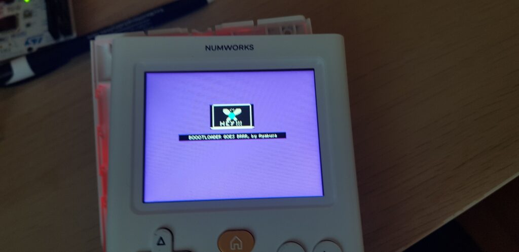
Now what would be great is to render images to the screen and once again there is a function for that at address 0x80037E4, I’ll call it
f_show_image(width, height, screen_y, *work_buffer, *compressed_image, compressed_image_size)
And here is how to use it:
show_some_image:
  sub.w  SP, SP, #0x2000  // We augment the stack, the value depends on the image but it should be big enough to avoid a buffer overflow

  mov.w  R3, #compressed_image_size
  mov    R2, #screen_y
  str    R3, [SP]       // We push both of our value on the stack
  str    R2, [SP, #4]

  add    R0, SP, #8     // This is our work buffer, just after the 2 args on the stack
  mov    R1, #width
  mov    R2, #height
  ldr    R3, =compressed_image_ptr

  ldr    R4, =0x80037E5 // Adr of f_show_image + 1
  blx    R4
This one was a bit more complex due to the stack shenanigans and the extra argument pushed on the stack, but I managed to reverse it properly and was able to show some image.
Note on the image format
The image format used by Numworks is a png image compressed with lz4, I used their image inliner which I tweaked a bit to get the raw binary
Here is the result after some trial and error:
Driving the keyboard
Sadly, for the keyboard I didn’t find any satisfying function so I decided to recreate a driver from scratch, I’m not gonna go into more details on how I implemented it here as it is quite similar to what I did in the previous post. But still, I had to test all connections to find all the pins and it was a really tedious task because the MCU is not on the same face of the PCB as the keys so I’ll share what I found:
           +-------+-------+-------+-------+------+------+
           | PC1   | PC9   | PC11  | PC4   | PC5  | PC6  |
           +-------+-------+-------+-------+------+------+
           | 1     | 2     | 3     | 4     | 5    | 6    |
+------+---+=======+=======+=======+=======+======+======+
| PA1  | A # left  | up    | down  | right | Ok   | back |
+------+---+-------+-------+-------+-------+------+------+
| PA0  | B # Home  |       | Pwr   |       |      |      |
+------+---+-------+-------+-------+-------+------+------+
| PA2  | C # shift | alpha | x,n,t | var   | tlb  | del  |
+------+---+-------+-------+-------+-------+------+------+
| PA3  | D # e^x   | ln    | log   | i     | ,    | x^y  |
+------+---+-------+-------+-------+-------+------+------+
| PA6  | E # sin   | cos   | tan   | pi    | sqrt | X^2  |
+------+---+-------+-------+-------+-------+------+------+
| PA7  | F # 7     | 8     | 9     | (     | )    |      |
+------+---+-------+-------+-------+-------+------+------+
| PA8  | G # 4     | 5     | 6     | *     | /    |      |
+------+---+-------+-------+-------+-------+------+------+
| PA10 | H # 1     | 2     | 3     | +     | -    |      |
+------+---+-------+-------+-------+-------+------+------+
| PA15 | I # 0     | .     | x10^x | Ans   | Exe  |      |
+------+---+-------+-------+-------+-------+------+------+
Booting an OS
We now need one last thing and it is to boot in an OS. We could try to use the original boot procedure, but this would also mean to deal with the signature check, and I don’t want this garbage in my bootloader so let’s do it by ourself:
disable_MPU:
  ldr  R1, =0xE000ED94    // address of the MPU_CTRL register
  mov  R0, #0
  str  R0, [R1]           // This disable all MPU region, probably not the safest

jump_slotA:
  ldr  R1, =0x90000020    // Address of the Slot A
  ldr  R0, [R1]           // Load the stackpointer
  msr  MSP, R0            // Set the stack pointer

  ldr  R0, [R1, #4]       // Load the reset handler
  bx   R0                 // Branch to slot A
First we completely disable the MPU (Memory Protection Unit) which would make our OS crash as it is responsible for handling what you can do in each memory region for example executing, writing etc…
Then we get the initial stack pointer and the reset handler (main function) using the ARM vector table of the slot and we boot using them
Vector_table:
0x0 - Stack pointer
0x4 - Reset handler
0x8 - NMI
0xC - Hard fault handler
...
The main issue I see is that by disabling completely the MPU, you expose yourself to the possibility that Numworks might relock your calc in a future update, but I don’t really see the point of them doing that as it would just mean a new unlock and some additional patching.
Conclusion
And that’s it we just made our own custom bootloader that let us do what we want with our calc! Sadly, I can’t share the binary since it would violate Numworks’ firmware licence, so you’ll have to make your own 😉
Once again this article is just for educational purposes and I wish no harm to Numwoks which has made a great calculator, and it was a blast to toy with their calculator!
I’d also like to thank TI-Planet and Critor, for sending me this calculator as part of one of their contest, and for their amazing forum which is a treasure of knowledge. And of course thx to the Upsilon/omega community for everything that they brought to this community such as this great wiki.
And as always thank you for reading my blog 🫶
~ See ya, Ayabusa
What you’ve done is so inspiring. Great job! ^^
Thanks, I appreciate it!
Is the modified bootloader sent by the recovery mode or something else?
Did your noped allow you to launch the official firmware or are you stuck on your purple screen?
For my personnal bootloader I did a small menu where you can select some options. One of them is to flash the slots with the default recovery mode. And another one is to access the stm32 recovery mode which allow reflashing the bootloader itself. And yes I can boot both slot A and B to access the official OS or the Delta custom firmware.
Impressive! Thank you for writing this interesting article! 🙂
I have just a small question, that might be dumb, but since everything was wiped out, why didn’t you start everything from scratch, instead of jumping from numworks bootloader into your code?
Thanks ! I tried in a previous attempt (see the first blog post to learn more). But it’s quite complicated, especially for the screen driver. So this allowed me to use the stock bootloader functions for example to show images on the screen with some RE 😉
Hello, I am trying to make drivers for my n0120, and I’m also stuck to the screen drivers, my problem is that the green looks grey, I would like to know if you had the same problem with the n0110, and if yes, if you have a solution
Nope, I’m not yet competent enough in embedded systems and especially screens. But good luck on your endeavor !
Do you know if newer batches of the N0120 get shipped with better RDP? Maybe level 2 or something? I tried connecting with the chip with a ST-Link and the official st software, but I could not connect to the calculator. It just started normally.
I have never heard of RDP2 being used on the n0120 (it will probably be the case for the scientific NW though). I recommend you follow this well written article from M. PARISSE:
https://www-fourier.univ-grenoble-alpes.fr/~parisse/numworks/khicasnw.html#sec7
It goes more in depth into the procedure. Maybe you missed something ?
Goodluck, I hope you’ll get it working !
Thanks, I got it working today. Now making a simple firmware to let the LED blink… Takes some time, I am new to ts
GG, I’m glad you got it working ! Good luck for your firmware 😉
Very nice post! Just a small typo you’d like to fix:
ldr R1, =0x90000000
should be 0x90000020
Thanks !